
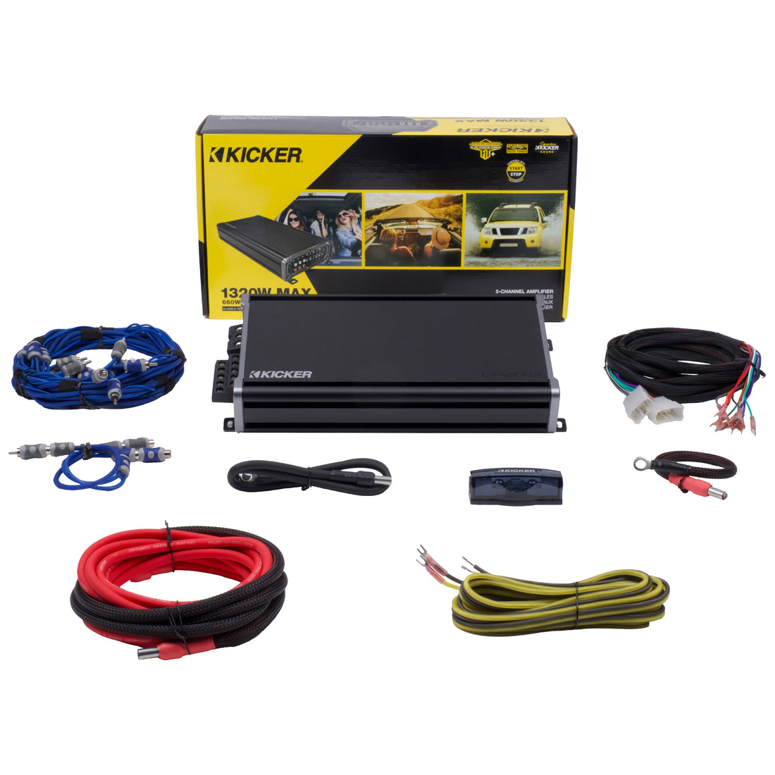
Welcome to the installation guide for your JBL Amplifier Bypass Bundle with Kicker 5 Channel Amplifier for the 2010–2024 Toyota 4Runner from Trail Grid Pro! This guide covers accessing the factory JBL amplifier in the rear cargo area, routing the bypass harness, and connecting the replacement amplifier beneath the front passenger seat. Read the full guide before starting.
Table of Contents
- Important Notes Before You Begin
- Tools Needed
- Step 1: Check Your Kit
- Step 2: Access the Radio
- Step 3: Remove the Front Passenger Seat
- Step 4: Remove the Passenger-Side Routing Trim
- Step 5: Access the Factory JBL Amplifier
- Step 6: Connect the JBL Bypass Harness
- Step 7: Route the Bypass Harness Forward
- Step 8: Connect the Radio’s RCA and Remote Leads
- Step 9: Route the RCA and Remote Leads
- Step 10: Route the Power Cable
- Step 11: Route the Ground Wire
- Step 12: Connect the Amplifier
- Step 13: Inspect the Wiring and Finish the Power Connection
- Step 14: Test the System
- Step 15: Set the Amplifier Controls
- Step 16: Reassemble and Complete the Final Checks
- Common Troubleshooting Solutions
- Contact Us
📢 Important Notes Before You Begin
Choose your cargo configuration: Step 5 has separate starting instructions for vehicles without a third row or sliding tray, vehicles with third-row seats, and vehicles with a sliding cargo tray. Follow only the matching branch, then continue with the shared cargo-panel steps.
Match your equipment: The original kit instructions refer to the Kicker 660.5 and CXA660.5T. Confirm your amplifier’s model and printed terminal labels before wiring. If your supplied parts or vehicle layout differ, contact us before modifying anything.
Subwoofer wiring: This bypass-harness installation uses red and orange at subwoofer positive, and black and orange/black at subwoofer negative. Do not substitute wire pairings from another vehicle or a separate subwoofer kit. The included yellow/black lead listed below is not used in the bypass-output connections described here; contact us before using it for a different subwoofer setup.
⚠️ Important: Battery, seat, seat-belt, and power-wire safety
- Turn the vehicle off. Follow Toyota’s battery-disconnection procedure before working on wiring, seats, or the seat-belt anchor.
- Follow seat-wiring precautions. Seat wiring may include airbag and occupant-sensor connections. Follow Toyota’s service instructions and required waiting period before disconnecting it.
- Protect seat wiring. Support the seat and release connectors correctly. Never let the seat’s weight pull on its cables.
- Keep amplifier power disconnected while wiring. Leave the power cable disconnected from the battery and keep the inline fuse removed until the installation is finished and checked.
- Use the specified fuse. Follow the amplifier and wiring-kit requirements for fuse rating and fuse-holder placement.
- Restore safety-critical fasteners correctly. Use Toyota’s specified procedures and torque for seats, seat-belt anchors, and removed cargo-tray hardware before using the vehicle.
- Get help if you are unsure. Use a qualified installer for seat wiring, seat-belt work, battery connections, or firewall routing as needed.
🛠️ Tools Needed
- 10mm socket, compatible ratchet, and extension
- 12mm wrench or socket for the battery-terminal hardware described in this kit
- 14mm wrench or socket for the seat, seat-belt, and cargo-tray fasteners described below
- 3mm Allen wrench for amplifier and fuse-holder connections
- Panel removal tool, preferably plastic
- Phillips-head and small flat-head screwdrivers
- Utility knife
- Wire fish or suitable protected wire-pulling tool
- Electrical tape
- Side cutters
- Zip ties
- Appropriate crimping tool for the supplied bullet connectors
- Torque wrench for reinstalling safety-critical fasteners to Toyota’s specifications
📝 Step-by-Step Instructions
Step 1: Check Your Kit
Inspect the packaging for shipping damage and lay out the parts:
- One Kicker 660.5 5-channel amplifier
- One plug-and-play speaker-wire/bypass harness
- Three pre-bundled 3-meter RCA cables
- One RCA splitter with double female adapters
- Red power wire and Kicker inline fuse block
- Black ground wire
- Yellow/black subwoofer speaker wire
- Four pieces of Velcro
- One male and one female bullet connector
- One supplied 10mm-head bolt
Contact us before starting if anything is missing or damaged.
Step 2: Access the Radio
Complete the battery and safety preparations above first. The trim procedure below describes the radio mounting arrangement in the original guide. If your aftermarket installation differs, use its removal instructions.
- Pull the two dash side panels straight back to release them.
- Grip the HVAC control panel at its knobs and pull the panel straight back.
- Release the wiring plug on the back of the HVAC panel.
- Use a panel tool to release the white wire retainer from the panel, then set the panel aside.
- Use a 10mm socket and extension to remove the four radio-bracket bolts. Keep them together.
- Hold the radio at the top and bottom and pull it straight back.
- Support the radio while accessing its connections. Do not let it hang by its wiring.
Step 3: Remove the Front Passenger Seat
- Remove the plastic covers from the seat’s mounting feet.
- Remove the four 14mm-head mounting bolts, two at the front and two at the rear.
- Carefully tilt the seat backward to reach its underside without stretching any wiring.
- Follow Toyota’s service procedure to release the seat connectors.
- Remove the headrest.
- With assistance as needed, lift the seat out and store it safely.
Keep the mounting hardware together. Do not switch the vehicle on with seat connectors disconnected.
Step 4: Remove the Passenger-Side Routing Trim
- Lift the front and rear passenger-side door-sill trim straight upward to release the clips.
- Turn the passenger kick-panel retainer counterclockwise to remove it.
- Gently release and remove the kick panel beside the passenger’s feet.
Step 5: Access the Factory JBL Amplifier
Choose the matching cargo layout below. The repeated cargo-side-panel instructions from the original guide are combined into one shared section after these branches.
No Third Row or Sliding Cargo Tray
Continue directly to the shared passenger-side cargo-panel steps.
Third-Row Seats
- Lift the carpeted cover to expose the five 10mm-head bolts noted in the original installation.
- Release and remove the plastic trim along the bottom of the rear hatch opening.
- Lift off the driver- and passenger-side corner floor covers.
- Remove the 10mm-head side-bracket bolt on each side of the third-row seats.
- Remove the four rear 14mm-head seat-bracket bolts.
- Release the front seat-bracket covers with a panel tool.
- Remove the four front 14mm-head seat-bracket bolts.
- Following Toyota’s seat-removal procedure, lift the third-row seats out through the hatch with assistance.
⚠️ Important: Confirm third-row fasteners before lifting.
The original guide identifies five 10mm-head bolts beneath the carpeted cover but does not explain their removal separately. Confirm the required fasteners and removal sequence in Toyota’s service instructions before lifting the seats or floor panels. Do not force an assembly that is still attached.
Continue with the shared cargo-panel steps below.
Sliding Cargo Tray
- Open the hatch and lift the lower plastic trim to release its clips.
- Use a panel tool to release the carpeted covers on both sides of the tray. Start at the ends toward the front of the vehicle and pry straight upward.
- Remove the four 14mm-head bolts on each side, eight total.
- With assistance as needed, lift the carpeted sliding tray out of the vehicle.
Continue with the shared cargo-panel steps below.
Shared Passenger-Side Cargo-Panel Steps
- Turn the passenger-side cargo-net anchor clockwise and pull it outward to release it.
- Remove the Phillips screw behind the anchor.

- Release the screw cover at the cargo-net attachment point and check for the fastener beneath it before pulling the panel.

- Release the screw cover directly below the storage pocket and check for its retaining fastener.

- Remove the 10mm-head fastener from the lower cargo anchors as fitted.

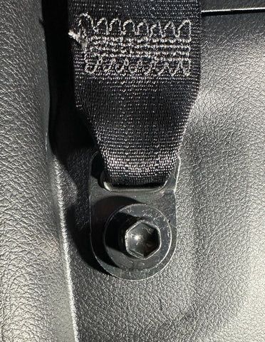
- Lift the lower rear passenger-seat cushion to reach the lower seat-belt anchor.
- Release its plastic cover and remove the 14mm-head anchor bolt following Toyota’s service procedure.


- Slide the recliner-handle cover toward the inside of the vehicle to release it.
- Remove the 10mm-head bolt behind the recliner handle.

- Check that all fasteners beneath the released covers are removed.
- Gently lift around the plastic cargo-panel edges to release the clips and access the amplifier. Stop if the panel is still held by a fastener.
Step 6: Connect the JBL Bypass Harness
- Locate the factory JBL amplifier’s 10-pin and 12-pin connectors.
- Press their release tabs and unplug them by the plastic housings, not the wires.
- Match each factory connector to the corresponding plug on the supplied bypass harness.
- Push each matching connection together until fully seated. Do not force mismatched plugs.
Step 7: Route the Bypass Harness Forward
- Route the bypass harness toward the front passenger-seat opening.
- Follow the factory wiring channel along the passenger-side door openings.
- Keep the harness clear of bolts, seat tracks, seat-belt hardware, and existing wiring.
- Use factory wiring hold-downs or zip ties as needed without crushing the wires.
- Leave enough slack at the amplifier end to make connections without pulling on the harness.
Step 8: Connect the Radio’s RCA and Remote Leads
RCA cables carry the radio’s audio signal. The blue remote lead tells the amplifier when to switch on.
- Connect FL and FR to the radio’s front-left and front-right RCA outputs.
- Connect RL and RR to its rear-left and rear-right outputs.
- Connect SL and SR to its subwoofer outputs.
- If there is only one subwoofer RCA output, attach the supplied Y-splitter, then connect both subwoofer RCA leads using the supplied adapters as needed.
- Use the supplied bullet connectors and a suitable crimping tool to join the blue remote wire to the radio’s amplifier-turn-on lead.
- Check that the connection is secure and insulated.
Step 9: Route the RCA and Remote Leads
- Route the bundle down the passenger side of the dash toward the footwell.
- Continue behind the upper carpet edge toward the bottom of the windshield-pillar area.
- Open the factory wiring-channel covers by releasing their tabs with a small flat-head screwdriver.
- Follow the channel to the front passenger-seat area.
- Pass the cables beneath the carpet and through the existing opening near the floor vents. Keep the vents clear.
Step 10: Route the Power Cable
Keep the battery end disconnected and the inline fuse removed.
- Plan the fuse-block position according to the amplifier and wiring-kit instructions.
- Connect the short shielded power-cable section to one side of the fuse block.
- Connect the long shielded section to the other side.
- Seat each protective grommet in its groove, tighten the connections with the appropriate Allen wrench, and fit the Kicker cover.
- Route the long cable along the inside of the driver-side fender toward the firewall, then across to the passenger-side firewall grommet, as described for this installation.
- Secure it away from heat, sharp edges, and moving components.
- Inspect both sides of the firewall grommet and identify clear rubber away from existing wiring.
- If an opening is needed, carefully make a small X only in that clear area. Some grommets have inner and outer membranes.
- Use a protected wire-pulling tool to guide the cable through without damaging the grommet or factory wiring.
- Route it behind the kick panel, through the factory wiring channel, and under the carpet to the amplifier location.
⚠️ Important: Never cut blindly into a firewall grommet.
If you cannot see and protect existing wiring on both sides, stop and use a qualified installer. Protect the cable from metal edges and maintain the grommet’s protective seal.
Step 11: Route the Ground Wire
- Route the supplied black ground wire under the carpet to the intended factory ground location under the passenger seat.
- Attach it using the supplied 10mm-head bolt.
- Keep the wire clear of seat tracks and mounting holes.

If you cannot identify the intended ground point, contact us rather than choosing an arbitrary seat or trim bolt.
Step 12: Connect the Amplifier
- Position the Kicker amplifier under the passenger seat.
- Check seat-track and floor-vent clearance and allow the ventilation space required by the amplifier manual.
- Plan to secure it with the supplied Velcro or suitable mounting brackets, but complete the wiring before permanent mounting.
- Connect the RCA leads by the labels below.
- Amp 1 Left: FL
- Amp 1 Right: FR
- Amp 2 Left: RL
- Amp 2 Right: RR
- Sub Left: SL
- Sub Right: SR

Connect the bypass harness’s speaker outputs:
Match each wire to the amplifier’s printed terminal label. Place each fork connector, the U-shaped metal end, under its terminal’s clamping plate and tighten the Phillips screw securely.
Rear speakers, Amp 2, bottom row in this installation:
- Left positive (+): green
- Left negative (−): green with black stripe
- Right positive (+): purple
- Right negative (−): purple with black stripe
Front speakers, Amp 1, top row in this installation:
- Left positive (+): white
- Left negative (−): white with black stripe
- Right positive (+): gray
- Right negative (−): gray with black stripe
Subwoofer outputs for this bypass-harness configuration:
- Sub negative (−), bottom row: black and orange with black stripe
- Sub positive (+), top row: red and orange
- Connect the black ground cable to the labeled ground terminal and secure it with the appropriate Allen wrench.
- Connect the red power cable to the labeled positive power terminal and secure it according to the amplifier manual.
- Connect the blue remote lead to the labeled remote terminal and secure it.
- Check for loose strands or connectors touching adjacent terminals.

Step 13: Inspect the Wiring and Finish the Power Connection
- Inspect every power, ground, remote, speaker, and RCA connection.
- Check that no cable can be trapped by trim, seat tracks, or mounting hardware.
- Confirm the fuse rating and fuse-holder placement against the amplifier and wiring-kit instructions.
- With the battery isolated and the inline fuse removed, attach the short power cable’s pre-fitted ring terminal to the positive (+) battery-terminal connection as directed by the vehicle and kit instructions.
- Secure the amplifier and restore the front passenger-seat wiring and mounting before powering the vehicle. Follow Toyota’s service procedure and specified seat-bolt torque.
- Restore removed seat-belt and rear-seat hardware to Toyota’s specifications before using those seating positions.
- Complete battery reconnection and fuse installation in the order required by the vehicle and amplifier instructions, only after all wiring is finished and checked.
Step 14: Test the System
- Start with radio volume low and amplifier gains at minimum.
- Switch on the radio and check that the amplifier powers on.
- Play a familiar track and check the front speakers, rear speakers, and subwoofer.
- Use balance and fader controls to help check the speaker locations.
- If sound is missing, distorted, or cutting out, stop and troubleshoot before increasing the volume.
Step 15: Set the Amplifier Controls
For the RCA-input arrangement described here, use these starting switch positions:
- Fader: ON
- Input Level: LO
- Sub Input: SUB
- Follow the Kicker manual’s gain-setting procedure for your amplifier and radio. Gain matches the radio signal to the amplifier; it is not an extra volume control.
- Choose a familiar track that will play for several minutes.
- Use a clean, undistorted radio volume for adjustment. The original kit procedure uses about 75% of maximum volume, but not every radio stays clean at that level.
- Starting at minimum, adjust Amp 1 gain for the front speakers using a small flat-head screwdriver, within the amplifier manual’s limits.
- Repeat for Amp 2, then the subwoofer gain.
- Reduce the gain and radio volume immediately if sound distorts or cuts out. Investigate before continuing.
⚠️ Important: Do not tune through distortion.
Clipping, distortion, or sound that stops can indicate a setup or wiring fault. Lower the volume and gains and check the installation. Ask a qualified audio installer if you are unsure how to set gains correctly. Make final radio EQ adjustments only after establishing clean sound.
Step 16: Reassemble and Complete the Final Checks
- Turn the vehicle and audio system off before finishing trim work.
- Confirm that the amplifier and wiring are secure and clear of seat tracks and vents.
- Close the factory wiring-channel covers without trapping cables.
- Refit the cargo-side panel, recliner-handle hardware, cargo anchors, covers, and original fasteners.
- Confirm the lower seat-belt anchor is restored to Toyota’s specified procedure and torque, without twisting or trapping the belt.
- For third-row vehicles, reinstall the seats, brackets, floor covers, and fasteners following Toyota’s service instructions and torque specifications.
- For sliding-tray vehicles, reinstall the tray, its eight mounting bolts, and covers according to Toyota’s procedure and specifications.
- Refit the hatch-opening trim, passenger door sills, and kick panel with its retainer.
- Reinstall the radio, its four bracket bolts, and the HVAC panel’s connector and wire retainer. Refit the dash panels.
- Confirm all four front passenger-seat bolts were tightened to Toyota’s specification, then refit their covers and the headrest.
- Check seat movement, seat locks, seat belts, and cargo-tray operation as applicable. Confirm no wiring catches or pulls tight.
- Test the audio and HVAC controls again. If a seat or airbag warning appears, stop and have the system checked.
Congratulations on installing your 4Runner JBL Amplifier Bypass Bundle!
🛠️ Common Troubleshooting Solutions
The Radio Works, but There Is No Sound
Check whether the amplifier powers on. Before touching wiring, isolate power using the vehicle and amplifier procedures. Inspect the remote lead at both ends, power and ground connections, bypass-harness plugs, and RCA input assignments.
The Subwoofer Does Not Play
Check the radio’s subwoofer-output setting and Sub RCA connections. Confirm Sub Input is set to SUB for this arrangement. With power isolated, compare the bypass-output connections with Step 12. Do not substitute the yellow/black lead or another vehicle’s wire pairing without confirming the intended setup.
Sound Is Distorted or Cuts Out
Lower the volume and gains. With power isolated, check for loose terminals, stray strands, damaged cables, and an insecure ground. Check ventilation and the amplifier manual’s protection-indicator guidance. Never fit a higher-rated fuse to hide a fault.
A Cargo Panel Will Not Release
Stop pulling and check the matching cargo-layout branch for remaining fasteners. Confirm fasteners beneath the cargo-net, storage-pocket, seat-belt, and recliner-handle covers before releasing the panel. Do not force trim that is still attached.
Your Vehicle or Harness Does Not Match
Stop before modifying anything. Send us your 4Runner’s model year, cargo layout, radio and amplifier models, and clear photos of the part or connection in question.
Contact Us
Need help? Use our contact form and include your 4Runner’s model year, cargo layout, radio and amplifier models, a description of the issue, and clear photos of the relevant parts.


